Designing a flat metal piece isn’t a big deal. It can be done with pretty much any vector drawing program, like Inkscape, CorelDraw, LibreCAD or similar, but the process is generally easier in SolidWorks.
The real power of SolidWorks comes when you have to design bent sheet metal, a task which looks simple but really isn’t.
Before any bending, you have to cut the sheet metal. That means you need a contour of the sheet metal to be cut, known as a flat pattern. As a standard feature, SolidWorks make this pattern for you, based it on your previously-designed model.
The best way to explain the design process is to show by example. In the following, we’ll first design a simple box and then prepare it to be manufactured in sheet metal.
Step 1: Opening a New Part Document
In SolidWorks, go to the File menu and click on “New”. In the window that appears, choose the “Part” icon and hit “OK”.
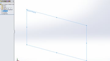
Step 2: Starting a Sketch
On the left side of the screen, you can find a feature tree. Click on “Front Plane” and a small toolbar will pop up. Choose the leftmost icon, the one that looks like a pencil.
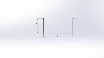
Step 3: Creating the Sketch
Create the sketch as shown in the picture. This will represent the outer dimension of our box.
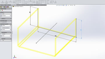
Step 4: Converting to Sheet Metal
On the main toolbar, choose the “Sheet Metal” tab. If you don’t see this tab, click the right mouse button on any other tab, and on the popup menu, check the “Sheet Metal” option. Then, proceed with the following:
- Click on the “Base Flange/Tab” icon and fill in the parameters.
- In “Direction 1”, enter “100 mm”. This is the length of our box.
- In “Sheet Metal Parameters”, enter “2 mm” for T1, which represents the sheet metal thickness, and “2 mm” in the next field for the radius.
The next parameter is very important. When metal is bent, it deforms. On the inside, metal is compressed, while on the outside, it expands. Due to this deformation, the thickness of material changes and the neutral axis shifts. This is represented with the K-factor, which is the ratio of the location of the shifted axis and the neutral axis.
The K-factor depends on the material, thickness, and bend radius. If you’re ordering parts to be made for you, ask the fabricator for this value. In our case, you should enter “0.365”.
To finish off this step, click the green checkmark in the top left corner.
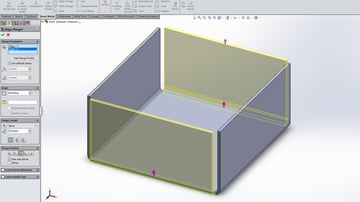
Step 5: Mirroring the Design
Now, let’s make the other two sides of the box:
- Click on the “Edge flange” icon in the main toolbar.
- Choose one of the bottom edges. SolidWorks will draw a yellow shadow of the new side.
- Enter “50 mm” for the flange length.
- Click on the top left list box, and then on the second bottom edge.
- Press Enter or click on the green checkmark.
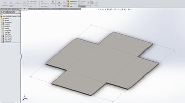
Step 6: Converting to a Flat Pattern
On the main toolbar, click on the “Flatten” icon in order to obtain the shape of the flat pattern.
You can now export this as a file for cutting, and the resulting piece of sheet metal will have the correct dimensions for bending into the shape of our box.
"tutorial" - Google News
December 21, 2019 at 03:43AM
https://ift.tt/35JfK17
SolidWorks Sheet Metal: A Beginner's Tutorial - All 3DP
"tutorial" - Google News
https://ift.tt/2N1vmVJ
Shoes Man Tutorial
Pos News Update
Meme Update
Korean Entertainment News
Japan News Update

No comments:
Post a Comment